Crius I2C GPS Nav Board – Programming via RS232 USB to Serial FTDI Board
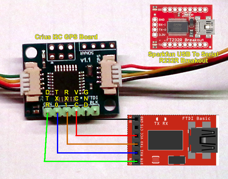
 I had an Adafruit UP501 GPS module laying around and wanted to get it working on my Quad. However, my serial connection is being used by a bluetooth module which left me with finding a way to get it working over I2C. I found the Crius I2C GPS module and this video which provides some great guidance on how to set things up. However, I was having trouble getting it programmed using the Sparkfun 232RL FTDI breakout board I had as I had not used it for some time and totally forgot how to make the connections between the two, so here you go.
The video above provides reference to the sketches and other bits necessary to configure the MultiWii flight controller, the sketch for the Crius I2c as well as reference to configure various GPS modules. I won’t go into detail on that.
[ad name=”GoogleAS728x90ImgOnly”]
- Load the Crius configuration sketch as described on the video and make the necessary changes.
- In the Arduino IDE, Select Tools > Board > Arduino Pro or Pro Mini (5V, 16MHz), w/ATMega 328 (note, the video above referenced another Arduino model, but that did not work for me)
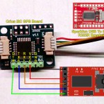
- Using the info below connect the FTDI adapter to the Crius unit.
- Program your Crius board. Done.
| FTDI | Crius |
| DTR | DTR |
| RX1 | TX0 |
| TX0 | RX1 |
| VCC (5V) | VCC |
| GND | GND |


Comments: