Juke – Custom Paddle Shifters – Phase 1
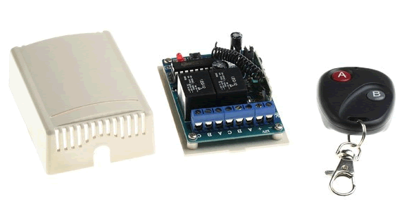
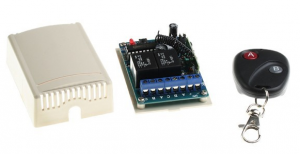 Not satisfied leaving well enough alone, I decided to add custom paddle shifters to my 2012 Nissan Juke. For those that aren’t in the know, the Juke has a sport shift mode where you can ‘bump’ the auto shift unit up or down to up/down shift. ..but that’s no fun… I wanted paddle shifters, and since there is no stock option, I decided to go the custom route. Before jumping into the project, the main hurdle to overcome was to figure out how to add the paddles to the steering wheel. In this case, the custom milled paddles I’m making would be mounted to the backside of the steering wheel and had to be wireless (for obvious reasons). I am aware that this is not conventional and that many paddles are mounted to the steering column, but I wanted them on the steering wheel. A suggestion led me to a RF wireless remote (pic) that fit the ticket. The plan is to embed the remote into the backside of the steering wheel, mod the buttons for ‘A’ and ‘B’ by adding wires out to the individual custom made paddle units.
Phase 1 – enable functionality for controlling manual mode shifting using an RF remote. This will be discussed here.
Phase 2 – Custom CNC milled aluminum paddle shifter units mounted to the steering wheel. Stay tuned
Phase 1:
Preface: If you want to try this yourself, you take responsibility for anything that may result from it. If you mess up, you risk frying one of the BCM which could cost you some serious coin. There is no guarantee that this will work for you, or of the long term affects. I know enough about electronics / car electrical systems to have confidence that this will work. If you don’t have this same confidence, then this may not be for you.
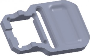
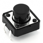
Since I don’t have many hobbies (not), I’ve jumped into desktop CNC milling and recently picked up a MyDIYCNC. My first project will be the paddles. I’ve modeled the unit as shown here. This will come in Phase II, but I wanted to show the end goal. The view here is of the backside of the paddle. The recessed area to the right is where the finger would rest when triggering the paddle. The blank area to the right is going to hold a small switch (see image). The switch will be mounted upside-down inside the paddle and will rest against the steering wheel. The switch itself will serve to both trigger a shift as well as provide the ‘spring’ to allow the paddle to triggered as the switch compresses against the back of the steering wheel. The far left side will be used to mount a tab to to attach the paddle to the steering wheel itself.
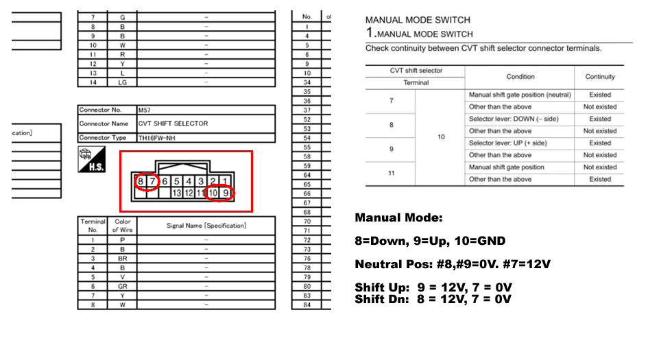
The Juke manual mode shifter has some built-in checks to ensure that it is in the manual mode state and that the ‘up’ and ‘down’ shifts are not phantom shifts. It does this with a few pins and an internal slide switch. Namely pins 7, 8, 9 and 10 (shown below). These pins can be seen circled red in the connector that mounts to the backside of the shifter pod. The manual mode shifting is monitored by the car computer to ensure than a shift took place and also determines which way. Reading the switching diagram to the right, the following can be interpreted:
- Manual Mode engaged: Pin 8 & 9 – no continuity between pin 10. Pin 7 – continuity to 10.
- Shift Up – Pin 9 continuity to 10, pin 8 &7 no continuity
- Shift Dn – Pin 8 continuity to 10, pin 9 & 7 no continuity
- Shift unit connector wire colours: pin 7=brown, 8=green, 9=grey, 10=yellow
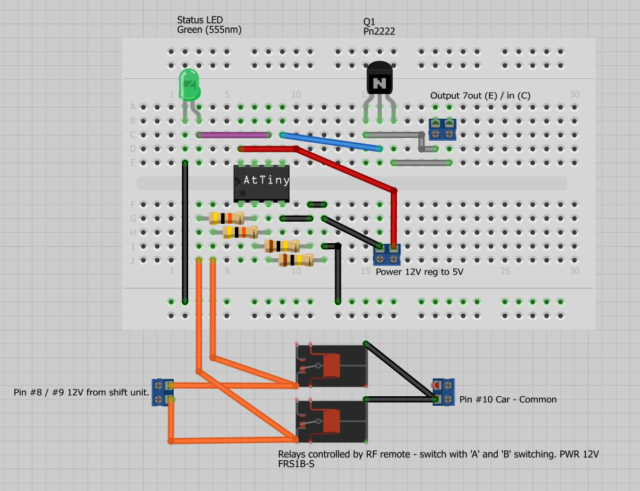
I wanted to do the mod as well as ensure the stock unit would still work as designed. To do this, I had to tap into these wires to mimic the action of the shifter lever, but not disable the shifter itself. The RF remote receiver has 2 relays – one for each button ‘A’ and ‘B’. This was perfect as it allowed me to run parallel lines off pins 8 & 9 and connect them to pins A of each relay. Pin 10 was connected to GND on both relays. The default state of the relay had no continuity between Pin 8 & 10 and pin 9 & 10 (as per spec). When the RF remote buttons are pressed, continuity to pin 10 is triggered from (8 or 9). The challenge was pin 7. Since pin 7 continuity needs to be broken when either 8 or 9 is triggered, it could not be connected to the relay as one of the relays would always keep continuity between 7 & 10 while the other relay would try to open it – not gonna work!
Jumping ahead, here is a demo of first part. The RF remote controlling the switching. Choppy video warning in 3…2…1….
The build:
To handle the pin 7 issue, I used an ATTiny85 Arduino micro controller to work as a NOT gate. It monitors pins 8 & 9 and, when either of them go LOW (no continuity), it would trigger pin 7 to go High (and vise-versa). The following image shows the circuit. The bottom shows the leads coming form pins 8 & 9 and the connection to the relays of the RF remote receiver. Recall that when in manual mode neutral state (still driving), pins 8 & 9 are Low and 7 is high. This is fed to a voltage divider for each of 8 & 9 to drop the voltage to a range between 0 – 5V. The ATTiny reads this, and triggers the output on pin 6 (top right in blue), which in turn triggers the 2222 transistor. On the car, the wire for pin 7 leading into the shifter was cut and leads were taken into the circuit (shown below top right for pin 7). One lead goes to the Collector and the other to the Emitter of the 2222. The idea is that the ATTiny serves as a trigger to set pin 7 High or Low.
Showing the wireless remote receiver and emitter. Pin 8 & 9 went to connector C on each relay while pin 10 when to both ‘B’ connectors. The ‘A’ connectors are not needed.
The below pic shows the ATTiny85 circuit connected to the RF receiver while testing. I had originally intended to build just use a quad NAND gate to make this work, but ran into difficulties with leaky voltage not triggering pin 7 to go Low. I also realized that there would be a timing issue. Consider that, when manually shifting by hand, it takes time (in hundreds of milliseconds) to go from the shifter neutral state to either an up or down shift. During that time, there is a mechanical switch that changes states for pins 7,8 and 9. However, when using the method here, everything is instantaneous. Once you touch a button on the RF remote and the relay is triggered, the switching is much faster than you can do with your hand. Once the relay is triggered, the output states of the pins switch from one state to the other and back very fast – too fast for the car to see them sometimes. I realized this when the RF remote was not working at first, but then when I held the button for a little longer, it worked. I introduced a delay into the Arduino sketch to allow for approx 600 ms time to hold the pins in their switched state (High or Low).
Showing some of the wiring. This is for pins 8, 9 and 10. Pin 7 missing as this is an early picture of the project. For pin 7, the wire is cut and a line is taken from each side. In the case of the other pins, I tapped into the line but left the wire intact. This is necessary to ensure that the shifter pod will still work. The pin 7 wire had to be cut or it would not be able to be triggered from the RF and Arduino units. BTW – pin 7 is the brown wire.
Phase I is complete – the circuit and RF remote allow the manual mode shifting to be controlled. I have yet to mill the paddles and hack the remote to get switching into the paddles – this is Phase II and will be coming in a bit. Check back again!
Source Code:
/*
Juke paddle shifter code - NOT gate. ATTiny85
Purpose: monitor inputs on A2, A3. When either go High, output on digital pin 0 to go Low. NOT gate
July 2012
D. Astolfo
*/

// On ATTiny85
int pin7Juke = 0; //pin #5
int led = 1; //pin #6
int shiftUp = 3; //pin #2 (note that pins are defined based on the ‘analog input text 3’ on the image at the below URL)
int shiftDn = 2; //pin #3 (note that pins are defined based on the ‘analog input text 2’ on the image at the below URL)
//http://hlt.media.mit.edu/?p=1695

void setup() {
//Serial.begin(115200);
// initialize the digital pin as an output.
pinMode(pin7Juke, OUTPUT);
pinMode(led, OUTPUT);
pinMode(shiftUp, INPUT);
pinMode(shiftDn, INPUT);

digitalWrite(pin7Juke, HIGH); //onstartup, pin7 needs to be supplying 12V.
}

// the loop routine runs over and over again forever:
void loop() {

//Serial.print("Val1=");
//Serial.print(analogRead(shiftUp), DEC);
//Serial.print(" Val2=");
//Serial.println(analogRead(shiftDn), DEC);

if (analogRead(shiftUp) < 900 || analogRead(shiftDn) < 900)
{
//will set pin 7 to LOW to tell the car that a shift up or dn has ocurred.
digitalWrite(pin7Juke, LOW);
blink();
//keep the pin low for a bit as the relays and electrics trigger much faster than doing this by hand through the shifter
delay(500);
}
else
{
//sets the pin back high again.
digitalWrite(pin7Juke, HIGH);
}

delay(100);

}

void blink()
{
digitalWrite(led, HIGH); // turn the LED on (HIGH is the voltage level)
delay(100); // wait for a second
digitalWrite(led, LOW); // turn the LED off by making the voltage LOW
delay(100); // wait for a second
}


Did you ever finish this ?
I did get it working. However, never really moved on to newer versions of the paddles. The electronics are still in place. I may jump back into this when I get my M3D 3D printer – I want to build some paddles.
So..how was it? any video ?
Hi. It’s been a long time since this was posted. Don’t recall if I took a video or not, but remember it worked and was fun while it lasted.
Hi, is there any more simple way not electric circuit way to do this? Like just directly connect the up and down pin to paddles shift and ground cables without bother the pin 7?
Hi, any way I can buy this device from you? Or is there any more simple way without using any electronic circuit device?
Hi Dave, just want to ask is there any simple way to DIY this paddle shifter without electronic component ? like just install paddle shifter parts or wiring but no electronic component involved?
Hi. Unfortunately, it’s been a long time since I built this, so don’t remember much other than what’s posted here. I am not aware of other ways to do this, but suggest you check Juke forums as someone may have done something else. To your other question, I have nothing for sale. This was a one-time mod I did years ago. 🙂