Nissan Juke – Footwell & Glove Box LED Lightning
Next on the block – adding LEDs to the foot wells and glove box. (Prev mods: LED Tails and Rear Passenger LED mods)
This mod can be especially useful this time of year up here on the 49th parallel since we are pretty much in darkness @ 5PM during November. All to often I drop something down near my feet and have to go looking for it. The light that casts from the map lights does not reach the areas down near the front driver/passenger foot wells, so I decided to add a few tiny LEDs to shed some love in the area when needed. In addition to this, the Juke comes with a MASSIVE glove box and no light. So, it was natural to throw a small LED strip in there as well. Both sets of LEDs are hooked up to a custom controller that uses an ATTiny85 and touch sensitive pins to control on/off states (I’m not one to go with status-quo, so the standard on/off switch would not cut it for me).
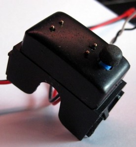
The switching unit (below) has 2 pairs of pins and 1 switch. The switch is used to control the rear passenger LED and is discussed here. Each pin pair make up a galvanic touch sensor that use the conductive abilities of skin to bridge the connection (reads – won’t work with gloves). Touch them once and the LEDs ramp up (on), touch them again to power them off. The top pair control the foot well LEDs, the bottom controls the glove box LED.
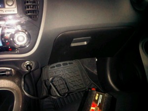
The switch controller installed – top left. Nissan was nice enough to leave us a blank, so naturally, I had to find a use for it!
LEDs:
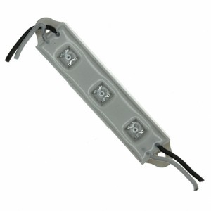
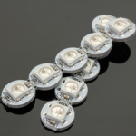
I’ve replaced the original LEDs with a set of Optek ones. Details here.
New:

[ad name=”GoogleAS728x90ImgOnly”]
Old LEDs:
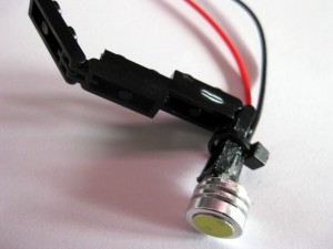
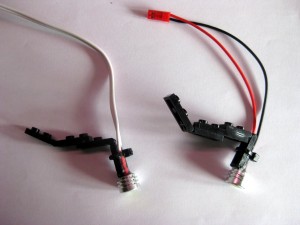
Below are the first run LEDs I used for each foot well. Yes, that is LEGO you see.. Have a look around this site to see why.. I can always rely on my LEGO inventory for parts when I need to do some sort of off hook-up, or mount. In this case, the pivot connectors allow me to swivel the LEDs to different positions – yet they are strong enough to hold their set position. They also allow me to quickly disconnect the LEDs in the event I have to remove something, such as the glove box. Some Goop glue and it’s all good.
Another pic showing the left and right foot well LEDs (old) .
Right footwell illuminiated (old):
Controller:
I did not take any pics of the controller, but it is loosely based on this. The idea being that the natural galvanic response of your skin acts to complete the circuit when touching the two touch pads/pins. This triggers a state change that the micro controller can interpret and act on. In this case, I have it watch the pin inputs for a voltage change and trigger the LEDs on (when the state is off) and vice-versa.
The code is pretty straight forward – monitor the 2 sets of touch pins for a change in voltage, when this happens to either, trigger the related LED output pin to ramp up to full brightness. Touch a pin set again, turn the related LED output pin off. A timer has also been used to automatically turn off either light after 5 minutes.
Code:
//uses button to dim LEDs in steps.  Coded toward ATTiny85
 //v6 updates to v5 include adding timer capabilities to allow LEDs to auto shut off after an elapsed time.  Will prevent from leaving lights on if not hooked up on accessory mode in car.

#include       // important note - MS2Timer2 affects PWM of PIN 3 and 11, so don't use them for PWM output.
 #include
 #include

//***********************
 //CONFIGURABLE VALUES

int tchValSens = 990;                      //val 1023 is open circuit.  0 is closed.  Dry fingers use 900, humid, damp, use 100

//************************

#ifndef cbi
 #define cbi(sfr, bit) (_SFR_BYTE(sfr) &= -_BV(bit))
 #endif
 #ifndef sbi
 #define sbi(sfr, bit) (_SFR_BYTE(sfr) |= _BV(bit))
 #endif

#define statusLED PB2                        //Digital In D1 - used to show timer countdown.
 #define ledCtrlrA PB0                       //Digital In Pin 1  MUST BE A PWM PIN (oddly my PWM pin#11 does not work) - controls IRF530 transistor > LED lights
 #define ledCtrlrB PB1                       //Digital In Pin 0  MUST BE A PWM PIN (oddly my PWM pin#11 does not work) - controls IRF530 transistor > LED lights
 int tchPadA = 3;                            //defined as Pin 3 (analog input 3) - physical pin ? on ATT85
 int tchPadB = 2;                            //defined as Pin 4 (analog input 2) - physical pin 2 on ATT85

int i = 0;
 int counterA = 0;                             //Counter used for dimming feature
 int counterB = 0;                             //Counter used for dimming feature
 int dlyTime = 20;                            //delay timer (for overall loop) in MS.
 int statCounter = 0;                         //counter for the status LED.
 int tchValA = 0;                            //Holder for tchValA
 int tchValB = 0;                            //Holder for tchValB

int ledStateA = LOW;                          //Holds the current state of the LED lights (HIGH=on LOW=off)
 int ledStateB = LOW;                          //Holds the current state of the LED lights (HIGH=on LOW=off)

int brightnessA = 0;                        //Brightness value for dimming the LED  0-255
 int brightnessB = 0;                        //Brightness value for dimming the LED  0-255
 int startBrightness = 0;                   //Initial brightness of the LED  0-255
 int statusLEDFlashDur = 100;                 //In Milliseconds - Flash period for MSTimer2 to flash the LED in ms.  100ms

long previousMillis = 0;                      //Store last time LED was updated
 long shutoffStartMillis = 0;                  //Store the value to start the shutoff timer from in Milliseconds.
 long shutOffDelayMS = 300000;                  //In Milliseconds - Determines how long to keep LED system on (after shutoff timer clicked) in Milliseconds  10000 (10sec), 60000 (1min) 300000 (5min)

//boolean sleepEnable = 1;

void setup ()
 {
 //Serial.begin (9600);
 pinMode(tchPadA, INPUT);                   //Setup the tchPadA as an Input
 pinMode(tchPadB, INPUT);                   //Setup the tchPadB as an Input
 pinMode(statusLED, OUTPUT);                 //Setup the statusLED as an Output
 pinMode(ledCtrlrA, OUTPUT);             //Setup the ledCtrlrA as an Output
 pinMode(ledCtrlrB, OUTPUT);             //Setup the ledCtrlrA as an Output
 }

void system_sleep()
 {
 sbi(MCUCR,PUD);                                  //Disables All Internal Pullup Resistors
 sbi(GIMSK,PCIE);                                   //Enable Pin Change Interrupts Interrups
 //add interrupt on 2 pins:
 sbi(PCMSK,PCINT3);                              //Changes Interrupt to pin 2 on physical chip (PIN 3 Analog Input 3)   (see http://hlt.media.mit.edu/wiki/pmwiki.php?n=Main.ArduinoATtiny4585)
 sbi(PCMSK,PCINT4);                              //Changes Interrupt to pin 3 on physical chip (PIN 4 Analog Input 2)
 cbi(ADCSRA,ADEN);                              //switch Analog to Digital Converter OFF
 cbi(MCUCR,SM0);                                  //Power Down Mode
 sbi(MCUCR,SM1);                                  //Power Down Mode
 sbi(MCUCR,SE);                                    //sleep Mode Power down enable (Sleep_enable(); should set this-- not tested yet)
 sleep_enable();                                      //Sets the Sleep Enable bit in the MCUCR Register (SE BIT)
 sleep_mode();                                       //sleep begins here
 sleep_disable();                                     //Coming out of sleep
 sbi(ADCSRA,ADEN);                             //switch Analog to Digital Converter ON
 cbi(MCUCR,PUD);                                 //Enables Pullup Resistors Again (this should happen anyway, but i have it here for now just in case, haven't fully tested yet)
 }

void flash(byte howmany, byte dly) {
 for (i=0; i < howmany; i++)
 {
 digitalWrite(statusLED, HIGH);
 delay(dly);
 digitalWrite(statusLED, LOW);
 delay(dly);
 }
 }

void rampLEDDownNoff(byte ledPin, byte lval, int dly, byte ledStateWhich)
 {
 //sleepEnable = 0;
 if (dly == 0)
 {
 analogWrite(ledPin,0);
 }
 else
 {
 flash(3, 60);
 while(lval > 0)
 {
 analogWrite(ledPin,lval);
 lval--;
 delay(dly);
 }
 //make it is all the way off
 digitalWrite(ledPin, LOW);
 }

if (ledStateWhich == 1)
 {
 ledStateA = LOW;
 }
 else
 {
 ledStateB = LOW;
 }
 //sleepEnable = 1;
 }

void rampLEDupOn(byte ledPin, byte lval, byte ledNormVal, int dly, byte ledStateWhich)
 {
 //sleepEnable = 0;
 if (dly == 0)
 {
 analogWrite(ledPin,255);
 }
 else
 {
 flash(3, 60);
 while(lval < ledNormVal)
 {
 analogWrite(ledPin,lval);
 lval++;
 delay(dly);
 }
 }
 if (ledStateWhich == 1)
 {
 ledStateA = HIGH;
 }
 else
 {
 ledStateB = HIGH;
 }
 //sleepEnable = 1;
 }

void loop (){

tchValA = analogRead(tchPadA);
 tchValB = analogRead(tchPadB);

/*
 Serial.print("touchValA: ");
 Serial.print(tchValA, DEC);
 Serial.print("  touchValB: ");
 Serial.print(tchValB, DEC);
 Serial.print("  TriggerVal: ");
 Serial.print(tchValSens, DEC);
 Serial.print("\n");
 */
 /*  continue to watch the touch for a capacitance change, when this happens determine
 *  what the intent is:
 *  a) user is holding finger on sensor, ramp LEDs up until they remove their finger.
 *  b) user tapped sensor, so turn lights on full (basic on/off)
 */

//using a threshold value to determine when the touch sensor is being pressed/tapped.
 //average normal values hover around 480-490, then when tapped, are about 680.  However
 //seems to be some sort of leak or interferance in the circuit as sometimes the circuit
 //can be made to jump to higher values and trigger the below statement to execute.
 //this was noticed by simply waving hand near the transistors/touch sensor.

if (tchValA < tchValSens)        //use this if modified R3 (2.2K) and T2 Emitter grounded direct to 0V. Arduino pin to Collector out of T2 (will be HIGH)
 {
 //when the sensor is either touched or pressed for a longer perior, the below statement triggers.
 //when a finger is held to the sensor, the time difference between current and previous Millis is very small
 //(as its resetting through every cycle which is approx 50ms) so, the first statement executes which causes the
 //LED power to ramp down from high to low
 //when tapped quickly, the intent is to toggle the LED on/off.  This is triggered when the current and previous
 //Millis are further apart. Then the state of the LED is checked and toggled to determine if it needs to be switched
 //on or off.
 //flash(3, 60);

//check state and turn led on or off -  if the LED is off turn it on and vice-versa:
 if (ledStateA == LOW)
 {
 brightnessA=startBrightness;
 counterA = 0;
 shutoffStartMillis = millis();      //get a start value to start the countdown from.
 MsTimer2::start();                  //start the timer to trigger the shutoff
 rampLEDupOn(ledCtrlrA, 0, 255, 2, 1); //5
 }
 else
 {
 brightnessA=startBrightness;
 counterA = 0;
 rampLEDDownNoff(ledCtrlrA, 255, 0, 1);  //10
 MsTimer2::stop();                    //shut off is reset any time user changes something
 }
 flash(3, 60);
 }

if (tchValB < tchValSens)
 {
 //Check on the second touch sensor
 //flash(3, 60);

//check state and turn led on or off -  if the LED is off turn it on and vice-versa:
 if (ledStateB == LOW)
 {
 brightnessB=startBrightness;
 counterB = 0;
 shutoffStartMillis = millis();      //get a start value to start the countdown from.
 MsTimer2::start();                  //start the timer to trigger the shutoff
 rampLEDupOn(ledCtrlrB, 0, 255, 2, 2); //5
 }
 else
 {
 brightnessB=startBrightness;
 counterB = 0;
 rampLEDDownNoff(ledCtrlrB, 255, 0, 2);  //10
 MsTimer2::stop();                    //shut off is reset any time user changes something
 }
 flash(3, 60);
 }

//this will shut down the LED after the ellapsed time period.  Rules - if the shutoffStartMilis has been set AND the time ellapsed is greater than the delay time. Shut off the LED
 if (shutoffStartMillis != 0 && millis() - shutoffStartMillis > shutOffDelayMS)    //if shutoff time has elapsed, turn the LEDs off  1000ms = 1 second
 {
 if (ledStateA  == HIGH)
 {
 rampLEDDownNoff(ledCtrlrA, 255, 10, 1);  //10
 }
 if (ledStateB  == HIGH)
 {
 rampLEDDownNoff(ledCtrlrB, 255, 10, 2);  //10
 }

shutoffStartMillis = 0;
 MsTimer2::stop();
 }

//we dont need to be polling with every cycle, so slow things down a bit. 20 original value.
 delay(dlyTime);

//pulse the status LED every second.  Use the delay value to calculate into approx a flash every second.
 //if (statCounter * dlyTime >= 1000)
 // {
 //  flash(1, 60);
 //  statCounter = 0;
 //}
//statCounter++;
// system_sleep();                                      //Runs the system_sleep() function
}





Hi,
Could you recommend any sites I could go to for a more beginner introduction in how to set something like this up?
There are number of good sites out there that provide all sorts of info. Some are forums, where you can ask for tips, others are ‘how-to’ sites. Below are some of the ones I frequent:
http://pcbheaven.com/
http://arduino.cc/forum/
http://hackaday.com
http://forums.adafruit.com/
http://hackedgadgets.com
http://www.instructables.com/
…and I just found this! http://octopart.com – great resource to look-up datasheets for parts. If there is something specific you are looking to do, drop me an email and I will try to guide you to helpful resources.
Very useful. Thanks for the info
A million thanks for posting this informaiton.