Dual LED Desk Light Controller – Arduino
I’ve been involved in microcontrollers for some time – but of the LEGO Mindstorms flavour (and BASIC Stamp to a lesser extent). Lately, I’ve jumped on the Arduino bandwagon. I’ve always had the natural nack to fix pretty much anything that has batteries or a plug running out of it. As the Arduino revolution has picked up dramatically over the past few years, so to has my desire to do DIY projects around the house. At some point in the future, we plan a kitchen reno. Part of that reno will the addition of under-cabinet LED lighting. Since that is far off, but I also had the need for better lighting in my office, I figured this would be a great time to proto something for the kitchen upgrade, while making something functional for the office. So, here it is..
Update Feb 2015: It’s been nearly 4 years since I built this project and it is still running strong. It is by far my most used DIY mod and gets used several times per day. The touchpad still functions as expected and the controller/LED’s are still good. I had one hiccup a few months ago where one of the channels (think it was green) had a connector come loose which resulted in the light emitting purple. A quick re-solder of that channel fixed things.
[ad name=”GoogleAS728x90ImgOnly”]
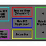
At first, I did not really have a plan. I knew I wanted some sort of switchless control of the LEDs, and to illuminate the main part of my desk. My initial prototype used a capacitive touch control using 2 copper tubes mounted on the project box. The idea being bridging the two tubes with your finger, the LEDs would dim up/down. You could also to a tap to turn them on (ramp up) and another tap to turn them off (ramp down). I was nearly done, but while perusing the web, I came across someone using an arduino and a synaptics touchpad together for another purpose – which got me thinking (smoke coming out of ears). I also found the need to want to control more than one light at my desk. I have multiple shelves and, even though the desk area can be illuminated, the shelf above are dark at night. This is also the place where all my electronic bits manage to find themselves when Im tinkering – and I often have to go fishing around for a flashlight to find bits I’m looking for. The addition of a touchpad provides many possibilities here.
When connected to the Arduino, a Synaptics touchpad can be used in two modes. Relative mode is the norm. It works like you would expect it to on a laptop. No matter where you put your finger and move it, your mouse will move from its current point in the direction you move your finger. Well, I’m not using a computer or moving a mouse around. I needed the unit to work in absolute mode. I need to know the exact X/Y coordinates of where my fingers were moving. Knowing this, I could create mapped areas to monitor in the Sketch and perform various actions when movement was detected in those areas. Thanks to this Instructable, the users Sketch contained the necessary commands to put the Synaptics touchpad in Absolute mode. The sketch uses the PS2 library as well. More on this later.
After testing a touchpad from my old and trusty Compact N600c, I decided to pickup a few extras from Ebay. I managed to pickup one from a Gateway W340UA and a Gateway Solo unit ($5 each). Both units had the Synaptics chip I was looking for, but I am sure there are many other Laptops that have similar units (eg IBM T42 does), and quick Google search will yield lots of results. I like this touchpad as it already has the arrow markers for the dimming feature that I wanted (more on this later re X/Y values). The next image shows the pinouts and trace paths for the Gateway W340UA touchpad that I used for this project. I have toyed with 4 different Synaptics touchpads and found them all very similar in their layout.
[ad name=”GoogleAS728x90″]
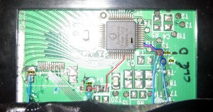
The pinouts are straight forward: +5V, GND, Data and Clock. Most sample sketches out there (especially the PS2 library) will have info on where to hook each of these up to on the Arduino. You can also download my sketch for this project further down below. Synaptics was even nice enough to give us DIY’ers little pads to solder to. These are evident for the Data and Clock points below. Note that, for the 5V power, you should track back as far to the ribbon connector as you can. There is at least 1 resistor and capacitor along the path to the pin on the Synaptics chip. Don’t bypass them if they are there. The Data and Clock pins are ok to go direct to the Synaptics pins. Also take note of the reference dot on the Synaptics chip – this typically refers to the starting location of PIN#1 on the chip.
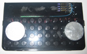
After soldering the pin connections on the back of the touchpad, I had to find a way to mount it. I thought of different ways to do this (embedding it on the desk, on the side, etc etc). Since I had a lot of metal mounting points aronund me (filing cabinet, side shelf beams, shelves), I just decided to put some magnets to the back of it. Of course, since my roots are with LEGO I could not fore-go the bastardization of a LEGO plate to mask the circuit board and soldering I had done with that fine blue wire (figure it must be 30-something gauge – it’s like thread!). So, I took to the dremmel and cut up a black plate and glued it to the back of the touchpad. Now, if I want to in the future, I can build any type of mounting system I want – using LEGO!
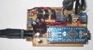
I am a minimalist when it comes to designing circuits. I don’t like large boxy control units. One day, I will perfect my SMD abilities and make these things even smaller. For now, I had to settle with a project box that I’m pretty happy with – approx 3″ x 2″ x 1″. I managed to cram in an Arduino Nano, 12V power connector, regulated 5V supply, 4x IRF 530’s (to control the LEDs), status LEDs and a number of connectors. It’s tight. I know what you Arduino junkes are thinking.. What a waste of a Nano. I’m cool with that. This is the first, and in future projects, I plan on creating my own Atmega based circuits. I’ve already cobbled together a staging board that I can use to program future chips. In the case of this circuit, I needed to use the PWM abilities of the 168/328 chips. I’m using all available PWM pins (4 of them). Again, Arduino junkies, I know what you are thinking – there are more than 4 PWM pins. Yes there are. However, I’m using the MSTimer2 library which kills the PWM of pins 3 and 11 for this project – I could have used another for the secondary LED lights, so if you have any ideas, share them up in the comments.
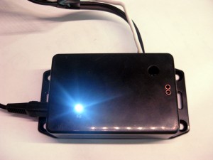
Looking at the Main Board below, I’ve labelled all the main parts. I used IRF530 MOSFETs to allow the Arduino to cleanly regulate 0-12V to each of the R, G, B on the main LED light bar and 1 IRF530 to do the same for the second LED light. In the case of the second LED light, I used a leftover strip of 3 RGB LEDs. In this case, I did not care to individually control Red, Green and Blue. What I did was simply use the IRF530 to power 0-12V to the LEDs on 2 wires. On the LED strip itself, I bridged R+G and from RG added a 330 Ohm resistor to Blue. This reduces the power output of blue which gives the light a warmer more natural light (not that bluish white light).
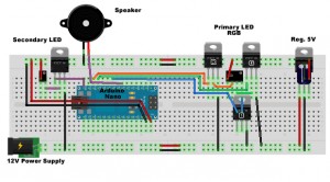
I’ve also included a breadboard layout created i Fritzing. Although Fritzing has some bugs, its a great app for rapidly producing usable breadboard, PCB and Schamatics of your circuits. I recommend it. I almost forgot to mention the speaker. This was a bit of an afterthought, but i had one laying around and thought it would be good to have some aural feedback when the touchpad was being used. Glad I did it. I have the LEDs ramp up/down and it can lead the user to wonder if it’s working as it can take a few seconds to complete its on/off cycle. This way, I can add beeps and chirps to the interaction of the unit.
The Sketch:
There are a few interesting things I thought I would point out about the sketch:
- To turn the Main LED on off – touch the center of the touchpad. The Main LEDs will ramp up to max brightness (more on this later). If they LED is on, it will ramp down to an OFF position.
- To manually control Main LED brightness, just slide your finger up/down along the right side of the touchpad (where the arrows are). There was an added bonus to the X values that Synaptics returned to the unit. Any touch to the area of the right band returns an X value of 8176. This way, my conditional check only has to check the 1 X value and a range of Y values. The Y values are mapped between 0 – 255 (the range of power to the LEDs)
- Delayed Time off – I have a feature that when the Main LED is on, clicking the top center will initiate a countdown timer of 10 minutes. After which the Main LEDs will turn off.
- Secondary LED on/off – clicking the top left corner of the touchpad will toggle the Secondary LED on or off (depending on its current state). I had to play around a bit with debouncing here as the loop cycle is ~20ms as it was catching multiple on/off states (even with fast finger taps). I used a simple delay in the code on this (did not want to get into fancy debouncing – will save that for the kitchen project)
- LED Brightness Save – I thought it would be cool to be able to save the Main LED brightness state. Using the right slider, you can adjust the brightness of the Main LEDs. When the desired level is reached, touching (and holding for approx 3 seconds) the bottom left area of the touchpad will save the brightness to EEPROM within the Arduino. The next time the unit is powered up, it will only ramp up to the saved max brightness value. This is persistent even if the Arduino looses power. The only issue is that I can only do it up to approx 100,000 times. Shucks…
Arduino Sketch: LEDLightDimmer11
/*
Control LED light strip via 12V power provided by parking lights (rear red). Additionally,
the actuation of the brake lights will also illuminate the LED strip at a brighter level to allow it to
enhance the effectiveness and visibility of the rear brake lights
Design:
12V main to power the arduino (ATTiny85) (via 3.3v regulated circuit). 12V main also directly powers the LED light strip.
However, the Arduino will be used to control a MOSFET via PWM to act as a light level controller. On start
the LEDs will automatically 'ramp up' to specific light intensity, but not 100% power. When the brake lights
are applied, the Arduino will detect this on an input pin and turn the LEDs on to full brightness, and then
back off once the brakes are no longer applied.
*/

byte ledMaxVal = 255; //Full LED brightness level - to be applied when brakes are on.
byte ledNormVal = 100; //normal LED light level.
boolean ledState = 0; //The current state of the LEDs. 0=off 1=on
boolean ledAtMax = 0;
//boolean brakeState = 0; //The current state of the brake detected on brakePin. 0=off 1=on
//int brakeV = 0; //Mapped value converted read from brakePin mapped from 0-1023 to 0-5V. Note Brake pin has a pull down resistor of 10K to have it read 0 by default.
int flashCounter = 0;
int brakeThresh = 500; //brake threshold. Pin is high. When brakes applied, pin drops to near 0V. value in mV

//Configurable values
const int LEDPin = 1; //output pin to control MOSFET switching to power the LED strip from 12V.
const int brakePin = 3; //pin that will detect when brake lights are on.
const int LEDstatPin = 0;

void flash() {
  digitalWrite(LEDstatPin, HIGH);
  delay(20);
  digitalWrite(LEDstatPin, LOW);
}

void rampLEDDownNoff(byte lval, int dly)
{
  while (lval > 0)
  {
    analogWrite(LEDPin, lval);
    lval--;
    delay(dly);
  }
  //make sure they are all off
  digitalWrite(LEDPin, LOW);
  ledState = 0;
}

void rampLEDupOn(byte lval, byte ledNormVal, int dly)
{
  while (lval < ledNormVal)
  {
    //give the LED a pulsing look
    //if (lval > 20) {
    //analogWrite(LEDPin,20);
    //delay(5);
    //}
    //comment the above to get rid of the LED pulsing.

    analogWrite(LEDPin, lval);
    //analogWrite(LEDstatPin, lval); //flash the status LED to show that the LEDs are ramping up.
    flash();
    lval++;

    //often, the brake lights will be applied on vehicle start. If this is the case, then just go to full power on the LEDs and
    //stop the remp-up procedure
    if (analogRead(brakePin) < brakeThresh) { // bail out on sensor detect
      analogWrite(LEDPin, ledMaxVal);
      ledState = 1;
      break;
    }

    delay(dly);
  }
  ledState = 1;
}

void setup()
{
  //Serial.begin(9600);
  pinMode(LEDPin, OUTPUT);
  pinMode(LEDstatPin, OUTPUT);
  pinMode(brakePin, INPUT);
}

void loop()
{

  if (ledState == 0) //LEDs are not on, turn them on.
  {

    rampLEDupOn(0, ledNormVal, 20);
    analogWrite(LEDstatPin, 100);
  }

  else if (analogRead(brakePin) < brakeThresh) //ledState would be 1
    //Optoisolator keeps brakePin Hi at 5V. When 12V applied (brake light), pulls brakePin low. Hi=1023. Just picked an arbitrary # of 500
    //if (analogRead(brakePin) < brakeThresh && ledState == 1)
  {
    //brakeState = 1;
    analogWrite(LEDPin, ledMaxVal);
    ledAtMax = 1;
  }
  else if (ledAtMax)
  {
    //brakeState = 0;
    analogWrite(LEDPin, ledNormVal);
    ledAtMax = 0;
  }

  //Serial.print("brkState=");
  // Serial.print(brakeState, DEC);
  //Serial.print(" brkPinV=");
  // Serial.print(brakeV, DEC);
  //Serial.print(" brkPinRaw=");
  //Serial.print(analogRead(brakePin), DEC);
  // Serial.print(" flsCnt=");
  //Serial.print(flashCounter, DEC);

  //Serial.println();

  flashCounter++;

  if (flashCounter == 20)
  {
    flash();
    flashCounter = 0;
  }

  delay(20); //give the processor some breathing time.
  //brakeV = 0;

}


awesome – good job
100,000 times is actually quite a few. At least if you aren’t doing it over and over. there is also the flash alternative. It’s not hard to hook up a sd chip, and they’re cheap.
Yup, my comment re the ‘only 100,000 times’ was sarcasm. I guess it was not that obvious. To date, I have saved the setting approx 4 times, I figure that gives me about 25,000 years before I won’t be able to do it 😉 Thx for the comment though.
This is really cool. I can get Synaptics trackpads for free out of the electronics recycling at my university, so I might do this for a desk lamp. They usually come with physical buttons, so I think I’ll use those for on/off, and maybe the tracking area of the trackpad to aim the task light using servos (though it might be easier to aim it by hand). If I use RGB LEDs, I’ll probably keep the color channels controllable so it can imitate some fancy iLED surgical lights (which might be a better use of the tracking area).