DualGrip-NXT Rover
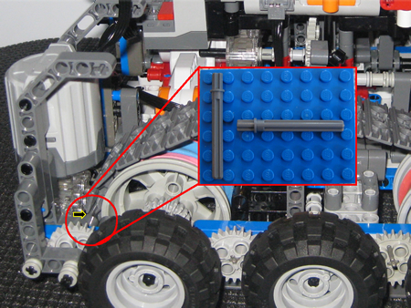
The following picture shows the deployment mechanism. . The NXT motor, drives through a 90 degree angle gearbox, through to a Technic worm drive, which then turns a 40T gear. The Technic gear is connected to two arms which are connected to each set of drive track units. When deploying, the track units are able to rotate. When I first began building this, I was not sure that the setup (click the image) would support the torsional stresses and weight of the robot. Turns out, it’s not an issue. The NXT motor, gearbox and 40T gear have no problem angling the tracks. From a code standpoint, the approach is straight forward:
- Poll the Accel sensor every 100ms. Read result.
- Make room for error and average the readings (the robot will shake and rattle which will throw off finer readings, so average the result – say every second).
- If Accel value is above threshold, trigger deployment of wheels (robot is climbing). Note – I have this setup currently only to trigger when climbing forward. When going backwards up an incline it won’t trigger. This can easily be changed. Also note that depending on which way the sensor is mounted, the threshold value you are measuring could be + or – . In my case, it is .
- I have attached a sample of the RobotC program below.
[ad name=”GoogleAS728x90″]
I had some of those cool 90 degree gearboxes on hand which worked well for DG.  Part of the NXT motor, and both gearboxes (shown right) are ‘floating’. Namely, the two gearboxes are not connected to the main frame of DG. The NXT has pins connecting it to the chassis at the back and the worm drive connects via the axle through it. Both gearboxes are supported only in that they are flush with DG chassis. The best part of this all is that it does not matter. Even with all the torque generated at these points, all the pressure is downward. Since their are already sitting flush with the chassis, it works just fine. You might argue that the torque then puts undue stress on the component holding the large gear, but I have not seen this and feel it is partly due to its structural design. Consider that the deployment mechanism has forces being applied equally from both sides (each wheel drive unit) and then downwards. The wheel units cancel out the side forces and the downforces are canceled by the chassis supporting the deployment unit. Notice that the wormdrive gearbox shown is the old one (that skips). Click the image.
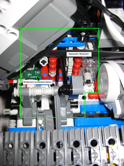
The following shows another angle of the wheel deployment mechanism. Also shown just below the NXT Brick is the Mindsensors Acceleration sensor. (click for large view):
[ad name=”GoogleAS728x90″]
Problem:
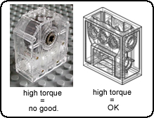
One problem that did arise was with the choice of gearbox. The below image shows two LEGO geraboxes. At first, I used the newer Technic gearbox (left). However, after some testing, I found that the worm gear would begin to slip due the torque being put on it. So, I swapped in an older Technic gearbox, which worked like a charm.
Next Problem:
 Admittedly, I tend to build my robots with little planning.
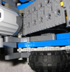
  Usually it’s a few visual and technical thoughts in my mind and then I just fire up and build. This also leads me to have to rebuild bits one or more times. The small image shows a top view of the drive gear system. Take note of the 24T gear and the lack of axle coming out where the tread link comes close to the edge. In earlier iterations of DG, I had a 6L axle running through there and it stuck out a bit. This was also fine for earlier versions of DG as it was longer and the treads did not come close to the 6L axle. However, as DG progressed, the wheel/drive system got shorter and more compact. What this resulted in was the tracks being very close to the L beam and 6L axle. The problem was, I needed the 6L axle running through there to connect the 24T gear – at the time there was a need to have it secured with a 1/2 bush as well. The 24T gear is driven by an 8T gear which is powered by the motor. So, there is a LOT of torque on this guy. When I fired up DG for the first time, there was a lot of racket as each track rubbed on the axle. Additionally, the torque caused the system to pull apart the 1/2 bush on the axle. As I was digging around for a solution, I came up with the Technic 5.5 axle with stop. Crisis averted! One of the issues was that when driving, the torque exerted on that gear required a full axle as well as the L beams to give it strength. The 6x axle was too long and even though I could have just pulled it away from the treads, that would not provide the ability to keep the whole assembly from flexing and coming apart. The 5.5 axle with stop allowed me to put the axle between two beams which were secured together and not need 1/2 bush on one end. Crisis averted.
Showing the deployment mechanism:
First run…
Another attempt:


That is cool!!
I understand this is in response to a LEGO challenge. But if you add the rubber tires to the side, what is the point of still having tracks? I mean, is there any situation where tracks would work better than the 6 wheels on the sides? Otherwise, I’d just make a robot with the 6 wheels, and get rid of the tracks altogether 🙂
@santi: In answering your below question – Yes, there is at least one situation where tracks would work better than wheels alone. I challenge you to build two similar robots (same size and wheel widths as DualGrip) – one with tracks and the other with 6 wheels as I have built it. Then, take those two robots and drive them on carpet making sure you try to do quick sharp turns in the process. Tell us which one turns faster without catching or buckling in the carpet? I am sure your answer will be the tracked robot is faster. Hence the reason for my challenge. Tracked robots are great for navigating all terrains. Tires can also meet these needs if you place the tires close together and your robot is not too wide. However, if you place a number of rubber wheels far from the center turning radius, you will see what I am talking about – they grab and bind while turning – especially on carpet.
If the LEGO tracks had rubber gromments in them, then I would not have been writing this as there would be no challenge and no robot to build. However, LEGO tracks are quite slippery on most smooth/hard surfaces. Rubber wheels satisfy the grip and climbing aspect, while the tracks satisfy the general turning and quick maneuverability requirements. Make sense?
Looking closely at your design, is the NXT also controlling the power-functions motor? how do you do that!?!? is it possible to generate an infra-red signal from the NXT to control the power-functions motor?
Yes, that is correct. If you read the “How Does it Work” section, I describe it in more detail there. Essentially, I am driving the robot FW/REV while the NXT and accelleration sensor determines the slope and causes the tracks to contract/expand automatically.
I was wondering the same thing about the wheels for climbing and tracks for driving. I would think it would be the other way around. Wheels for speed on the ground and then tracks for climbing hard obsticles where the tires might get stuck.
I do see where tracks would help on a 360 spin, where tires would need to take a big circle turn if you have room. (side note: discovery had a tank build off, one team used full tracks second team used small tracks with wheels in front. the tank track style could not 180 spin where the small track with wheels took less time. I think bad track design on the first teams part. But it was intresting to see it have such a hard time turning in dirt.)
Maybe a 4 wheel steering design would make turning easier and still be able to climb and move fast.
Thx for the comments. What you are saying would be true in a real-life setup. However, if you have these LEGO tracks, you will find that they are hard smooth plastic and have little to no grip on many surfaces (especially tile / hardwood). So, in LEGO reality, the tracks are better for quick turns etc, and rubber tires for climbing as they have sticking power.