WiFiCamBot
Jan 2008:
WifiCamBot was one of my adventures in building a robot that could be remotely driven around while transmitting video via a live feed through an IP-based network camera wirelessly.

The idea came from my wanting to do something simple. Survey underneath my deck to see what sort of critters etc were making a home there. The deck was high enough for a rover-like vehicle to fit and drive around. I did not want to have wires tethered to the system, so I used a Panasonic BL-C30 WiFi camera with a built-in webservr to transmit live video via the web.
In this case, I have a webserver where I created a subdomain specifically for the camera to broadcast its info to. Loaded the Java components to receive the streaming video and render it on the site. The site also allows for remote control of the camera via WiFi. So, the entire robot, power and electronics are all onboard. There were a few challenges with this approach. 1) Power – The Wifi camera required 12 volts dedicated power. I did this by wiring 2 battery packs together in series (required a custom modified motor wire). This also added a fair bit of weight to the robot. In total there are 2 battery packs for the WifiCam and 1 for the PowerFunctions motors. That is 18 AA batteries. No worries though – the PF motors still have lots of torque.

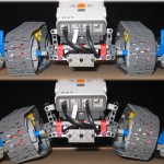
There are a total of 3 motors. Two large PF motors are used to drive the tracks. I wanted to try something different for mounting, and used 2x 90 degree angle gear trains with an angular mounting bracket. There are more pictures that show this. The mounting is unique, yet strong and holds up well. In addition to this, it is also out of the way which leaves room for other components. The WifiCam in particular requires a lot of room as 1) its big, and 2) it needs to rotate (using a smaller PF motor).

[ad name=”GoogleAS728x90″]
A close-up of the Panasonic WifiCam. It is large because the camera can be panned and tilted. There are 2 built-in motors to do this which makes for a larger unit.


Another view of the rover. As can be seen, there is lots of space up front for mounting of other components. I experimented a bit by adding a “prodding” arm using the fourth (small) PF motor. The idea was that I suspected that bees were building a nest under the deck and I would used this to knock it down while I stood inside with the screen door closed.

…a frontal view showing open space for add-ons as well as the WifiCam power connector.

A rear-view shows where all the mechanics are. The camera’s own up and down rotation was limited by approx 90 degrees. As the rover need to look straight up at times (to watch the prodding arm), I needed more movement. So, I mounted the camera to a pivot and used a small PF motor and a cam to allow for further rotation. The PF motor enters the clear worm drive unit. This is useful s it geared down for lots of torque as well as small.

…another view of the rear drive PF motors.

…and a view from underneath showing the 90 degree gear transfer cases.
[ad name=”GoogleAS728x90″]

The bottom of the rover was built to provide clearance to get over small rocks etc.

Rate This Post:


Comments: