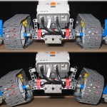
TrackerBot
You would think I have a template for “room-navigating” robots… TrackerBot evolved from the recent PicoCam robot I created. After I had finished PicoCam, I decided I wanted to try something with tracks. TrackerBot and PicoCam share similar intelligence, with TrackerB![]() ot having some slight improvements. The general idea is that it will navigate a room using a variety of sensory input for obstacle avoidance. There are 3 Cybermaster touch sensors, 1 DIRP light sensor and 1 line following standard Lego light sensor.
ot having some slight improvements. The general idea is that it will navigate a room using a variety of sensory input for obstacle avoidance. There are 3 Cybermaster touch sensors, 1 DIRP light sensor and 1 line following standard Lego light sensor.
The DIRP light sensor (seen here at the top), does most of the work. It is set-up as a light sensor and detects left, center and right objects. It does a pretty good job of making sure TrackerBot does not hit things. The Cybermaster touch sensors are used to detect objects that are low, at the back or out of the line of sight of the DIRPD sensor. They are wired such that all 3 sensors can be placed on one port (more on this after).
TrackerBot is also equipped with a pinhole wireless colour camera. It can broadcast live colour video with sound to the receiver and show its progress on TV. It is more of a proof of concept than any real function. Read on for more details…
A side view of the robot showing the rear collision sensor, drive motors, and the tracks (non-Lego). Yup – I broke the rules. The tracks on TrackerBot are from one of those cheap remote control battle-bots sets. I picked the set up for next to nothing solely for tracks. These tracks fit well with the wheel hubs shown and are nice and flexible. They grip well and are about twice the length of Lego rubber tracks.
Here is a rear view showing the bump sensor. One of the 3 Cybermaster sensors are used to detect collisions from the back. This sensor uses an elastic band to keep it from triggering with movement. This is due to its design, which makes it very sensitive.
A side view of the robot highlighting the front bumpers. The bumpers use Cybermaster touch sensors to detect left and right. The yellow cross tubes are used for center collision detection. In many cases, they will cause both sensors to be triggered at the same time. Because of the ability to configure these sensors to return various readings depending on which was hit, it is possible to code in reactions to front, left, center and rear collisions. More on this in the following pictures…
[ad name=”GoogleAS728x90″]
A close-up of the right Cybermaster sensor. Each of these sensors has a resistor in it, which, when connected together, and set as SENSOR_MODE_RAW in NQC, can be configured to return different values between 1 and 1024 when triggered. The following is a sample of code used to tell the program which sensor is triggered
 while(true){<br />

 v = TOUCH_SENSOR;<br />

 if(      v > 800 )  touch_sensor_state = 0;   //nothing is happening<br />

 else if( v > 740 )  touch_sensor_state = 1;   //left side<br />

 else if( v > 730 )  touch_sensor_state = 4;   //back<br />

 else if( v > 705 )  touch_sensor_state = 2;   //right side<br />

 else if( v > 580 )   touch_sensor_state = 3;   //both left and right<br />

 else                touch_sensor_state = 5;<br />

 Wait(20); }//give the CPU a break.<br />
This is a close-up of the touch sensor wiring configuration. I included partly because I keep forgetting how to set them up every time I want to do this sort of thing. Well, now I can just refer to my site instead of scouring the web for the solution. The configuration shown is for 3 Cybermaster sensors. The idea is to wire them in parallel. Doing this will ensure that regardless of which sensor is triggered, the resistance will change and can be read. To determine the values for the above code (sample), connect each sensor, trigger each one separately (and in combination), writing down the readings. The readings vary depending on which order the sensors are connected (as they have different resistances).
This is the base of the robot showing the tracks and the line following light sensor. The base was built using a combination of studded and studless appraoches. Both track units are studless and modular. They are connected with several friction pegs and can be removed in a snap. The base is built using studdend technology. This allows for other components to be easily mounted. Reads – Lego has yet to come up with motors that will integrate well with studless beams. Reads further – give us some holes for friction pegs! 🙂
The sensor has not been coded into the program as of yet. The general idea will be to have to robot do typical navigation and avoidance routines, and, if it comes across a black line, it will switch to line-following mode.
[ad name=”GoogleAS728x90″]
![]()
A side view of the base. This shows the non-Lego tracks at a closer view. They perform fairly well for traction and glide well in the wheel hubs shown. They are approx. 2x the size of standard Lego tracks which makes them well suited for cranes etc. I pulled them from a BattleBot set I got for next to nothing. The only problem is that, because of their size and length, it makes it particularly hard on the motors to turn the robot. The robot is geared with 12 to 24 wide gearing so that it can move relatively fast. I would recommend doubling up the motors on each side to give it more power.
Rate This Post: [ad name=”GoogleAS728x90″]


Comments: