Solar Charger Project
At some point I would like to use solar energy to supplement our home power usage.  Of course I was not going to jump into a full-out solar power array on my roof and out myself thousands of dollars without fully knowing the risks and potentials of photovoltaic solar power in my area. Instead, I decided on a proof-of-concept project – a small 10Watt 12V solar charger.
Before getting into detail, here are some difficult facts that I am dealing with:
- I live in Southern Ontario – daylight benefits are shorter in the winter – both due to limited sunlight in the daytime and clouds due to snowy winter months.
- My timing has had this project go live in the worst possible time – beginning of winter, shortest days of the year, and snow due to start falling anytime = limited light conditions.
- It’s cold, and its only going to get colder. The solar cell, battery and charge controller will be outside – this will allow me to evaluate how well they will perform in colder conditions.
Project Materials (all prices in CAD):
- 12V 12Amp Hour Lead Acid Sealed Battery: $50
- Sea Sense Marine Battery Box: $20
- Solar Charge Controller: $32
- 10 Watt Solar Cell: $55
- 75 Watt Inverter: $10
- Various Connectors/Nuts/Bolts/Other materials: $20
- Wire Line (40ft): $30
- PVC Piping: $10
[ad name=”GoogleAS728x90″]
Details:
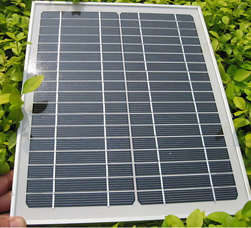
I decided to go with a 10Watt solar cell. The unit is quite small measuring 13.8″ x 11.2″ x 0.7″ with a max voltage of approx 19V (although it hit 21.5 today), a max current of 0.58A.
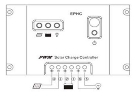
The general concept of a solar charger is that you have a power source (solar cell), a battery, a load and a controller. The controller is the brains of the system with all components linking to it. The following image shows the inputs at the bottom. The solar cell to the left, battery in the middle and the load to the right. All components are 12V. The load can be a 120V inverter.
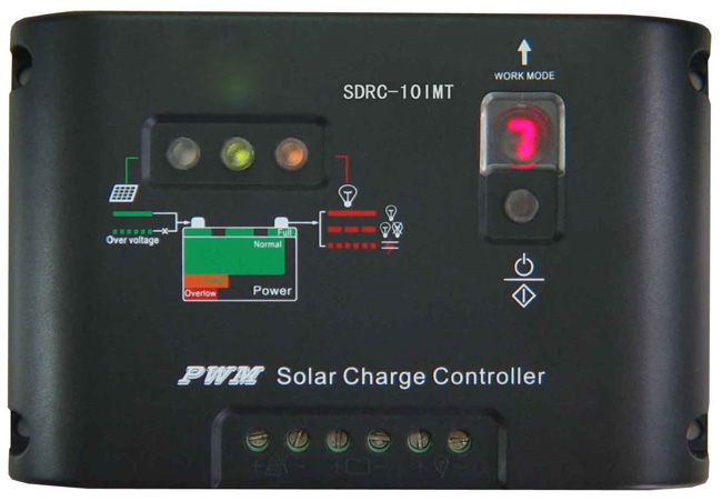
 The controller that I used also doubles as a timer of sorts. It can be programmed in a number of ways that allows you to turn the output (load) on as follows:
- load on all the time – the output load can be set to always be on and drawing power.
- load on after sunset – after the voltage drops off below specific voltage (e.g. 10.5V) for a prolonged period (eg 10 minutes uninterrupted), the system can turn the load on for a set number of hours (1-10 hours)
- manual load mode – allows me to hit to button to turn the load on manually.
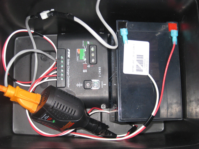
I used a marine battery box that allows me to keep the components protected from the elements while still allowing them to release heat as well as any hydrogen to escape from the battery and charging processes. The current layout still needs some work. I intend to securely mount all the components as well as get the inverter setup so it can be plugged in externally to the box. I am stuck with this as I want to box to be resistant to the elements while being versatile enough to allow me to connect to it. At some point, I also plan on connecting a digital volt metre inline so I can assess the charging status and power draw on the system while its in use. More work needs to be done here..
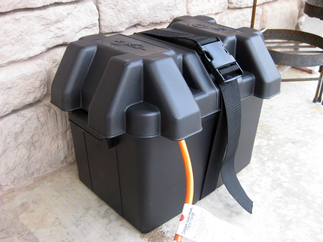
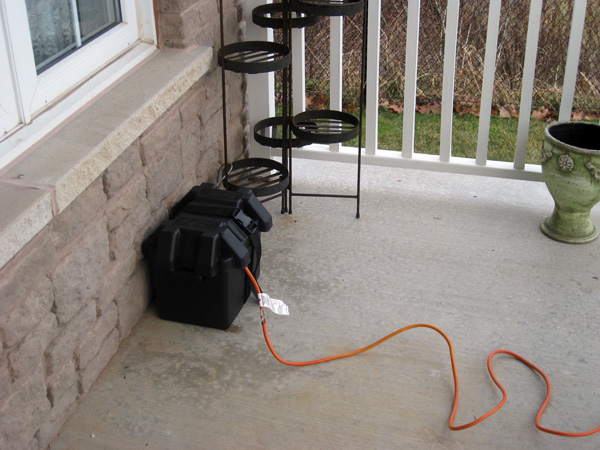
Some pictures of the battery box on my porch. The lid that has venting built in to allow the internals to breath. I plan on adding some of that nylon cleaning pad at the top to keep pests out but to allow it to breath.

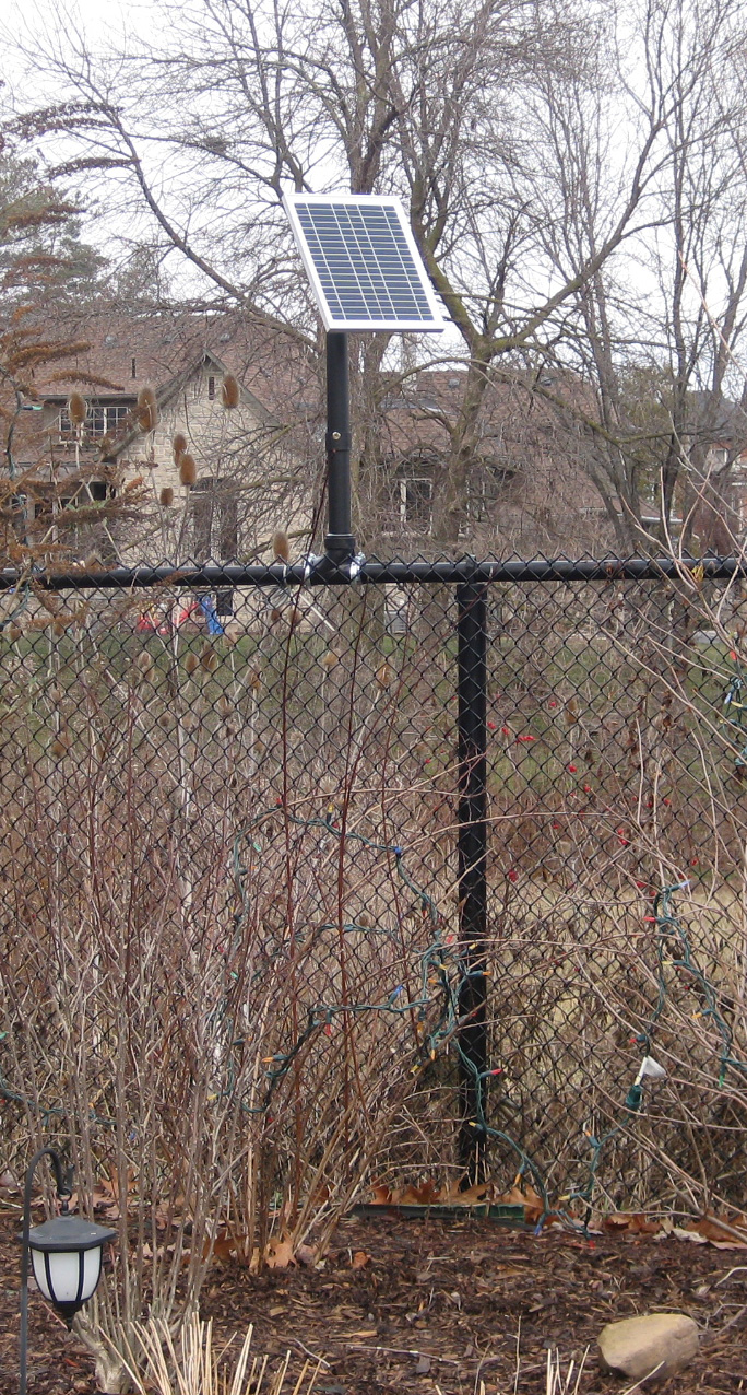
I am fortunate to side onto a ravine area and have a property line that allows me to install the panel away from obstructions to maximize the light exposure it will receive. The picture below shows the current setup. However, I suspect that this will have to change as it’s a bit of an eyesore – especially as we are entering the winter months. In the summer the plants and shrubs would obscure the mechanics somewhat and make it a little less visible to the neighbours.
Specifications:
Solar Charge Controller:
|
Rated Charge Current |
10A |
|
Rated Load Current |
10A |
|
Work Voltage |
12/24V Auto |
|
Over Load,short circuit protection |
1.25 rated load current 60 sec,1.5 rated loads current 5 sec,over load protection action,≥3 rated load current short circuit protection action |
|
No load current |
≤6mA |
|
Charging Circuit Voltage Drop |
≤0.26V |
|
Load circuit voltage drop |
≤0.15V |
|
Over voltage protection |
17V X2/24V |
|
Work Temperature |
Industry/State-35?to +55? |
|
Boost charge voltage |
14.6V,x2/24V,(Keep 10 min) |
|
Direct Charge Voltage |
14.4V,x2/24V,(Keep 10 min) |
|
Float Charge Voltage |
13.6V,x2/24V |
[ad name=”GoogleAS728x90″]
Solar Cell:
- Maximum Power: 10.3W watt
- Maximum-power Voltage: 17.8 volt
- Maximum-power current: 0.58 Ampere
- Open-circuit voltage: 22.1 volt
- Short-circuit current: 0.69 Ampere
- Size: 350 x 285 x 18 mm ( 13.8″ x 11.2″ x 0.7″ )
- Weight: 1.25 KG (2.8 pounds )
- Surface of the cell: 125 x 125 mm
- Temperature: -40 ° C / +80 ° C
- Temperature coefficient of Pm (%): -0.47 / ° C
- Temperature coefficient of Im (%): +0.1 / ° C
- Temperature coefficient of Vm (%): -0.38 / ° C
- Tolerance: + / -5%
Rate This Post:


 (2 votes, average: 4.50 out of 5)
What are you planning on testing with the setup? it would be ideal for an indoor and/or outdoor lighting system if you used LED lights that would power straight from the 12v battery.
Also it’s worth testing how much power the inverter uses even when it’s not powering anything, I tested a cheap 150watt car inverter on my little solar setup with a 24watt panel+large battery, and the inverter used 5 watts without even powering anything.
Good questions. Right now, I am running a 75W inverter and then 4 sets of outdoor LED lights. Unfortunately, they are 120 V lights (must be wired in series as there is no transformer). It would be better if I could forgo the inverter and power 12 items. Right now, I am just getting my feet wet with the technology. I have already been told that my current setup will run the battery down and never maintain a charge. However, I just purchased a kill-a-watt unit and will be testing the load the LED lights put on the system. Another option I am considering is hooking an IP camera up to the system to serve as a security system.
A cheap way of monitoring the power going into or out of the battery is through a couple of cheap multimeters, set one up reading the voltage of the battery and the other measuring the amperage of the power from the solar panel or the load from the inverter, then simply multiply the battery voltage by the amps to get the watts. A kill-a-watt won’t tell you how much energy the inverter is using from the battery – just how much it’s putting out.
http://www.solarpowerforum.net has, despite the banners making it look very commercial, a lot of information and knowledgable people on the forums, useful if you’re intending to run a device 24/7 forum members will usually gladly help out with calculations of what size battery banks & panels you need (often people discover it’s much more than they imagined)
Thx for the tips. I visited solarpowerforum already – its a good resource for information on the subject.
Thanks. Very interesting posting.
Man that’s cool. I love DIY – it’s such a cash saver and … like they say if you want it done right, you gotta do it yourself.
Hi, great post I want to do something similar and I bought the same solar charge controller but I can’t find the “load on all the time” mode, do you know the number of that mode??
To have the the output on all the time, you have to select setting # 0. (instructions state: “Dusk to Dawn, light is on all light”) – yes, the last word was “light”. Something got lost in the translation of “night”. To have the light on for a preset time period:
# 1 -1 hr light after sundown, #2 – 2 hr light after sundown and so on. As you change the numbers they go from 0-7, then start at 0 again but with a ‘dot’ to the bottom right effectively giving you 16 settings. eg 1 ‘dot’ is 9 hours light after sundown. 7’dot’ – Test mode – lights on after no light detected, off after light is detected.
I just found your blog on Ask Jeeves, a really good read.